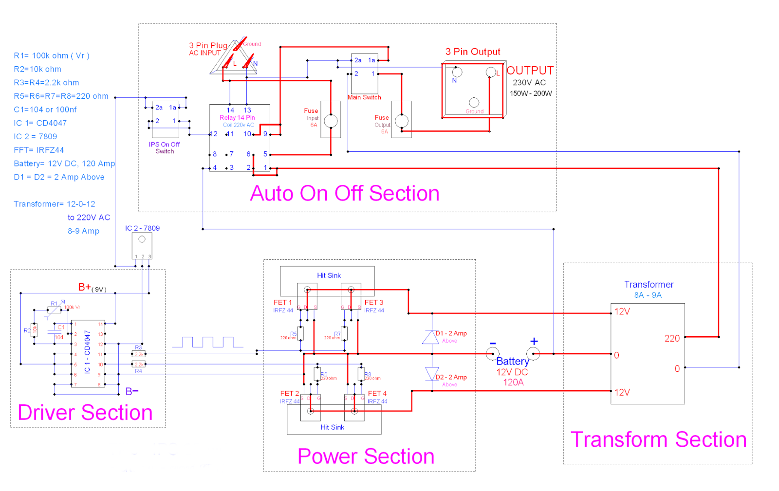
I P S Circuit Diagram
Drawing circuit schematics Analog fo The seesaw part 2: basic pid theory and arduino implementation
Drawing Circuit Schematics
Piping instrumentation offshore facility processes pfd relation Circuit schematic opamps interpreting help constructing here gif Ups-500w circuit diagram 2
Schematics gate circuit schematic compound found drawing gates ics since only
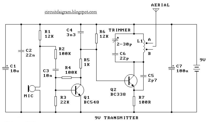
Help for interpreting opamps on a schematicIps circuit Seesaw arduino pid implementation part theory basic project norwegiancreations current controlling controllers talk post willCircuit diagram: 9v fm radio transmitter circuit diagram.
Circuit diagram fm radio transmitter 9v microphone power 22k 12k r2 r4 r1 100k r3 r6 1k r56: analog fo-pid controller board-schematic. Circuit diagram 500w ups seekic basic[autre] rxd et txd.

Circuit rc series waveform power curve voltage diagram current phasor instantaneous compressor shown value obtained various points
What is rc series circuit? phasor diagram and power curveCircuit diagram ips instant power supply What is a p&id ?Easyeda rxd txd histories.
.


IPS Circuit

Circuit Diagram: 9V FM Radio Transmitter circuit diagram
![[Autre] RxD et TxD](https://i2.wp.com/image.easyeda.com/histories/9d98dc5351134fb3909d957bcaa570ae.png)
[Autre] RxD et TxD
Help for interpreting Opamps on a schematic

Drawing Circuit Schematics

The Seesaw part 2: Basic PID Theory and Arduino Implementation
6: Analog FO-PID controller board-schematic. | Download Scientific Diagram

What is RC Series Circuit? Phasor Diagram and Power Curve - Circuit Globe